The publisher of HDDNews.pl is affiliated with the developers of HDDSuite. This article is based on the program documentation and demonstration version.
A horizontal directional drilling design is usually put together in several separate tools: the trajectory is drawn in CAD, drilling fluid rheology is calculated in a spreadsheet, pull-in force in a calculator, and the geological profile and report are assembled by hand. HDDSuite brings these tasks into one web application in which the output of each step becomes the input of the next. The trajectory from the longitudinal section feeds the hydraulics, and the hydraulics feed the hydrofracture assessment.
The program is aimed at HDD designers, site managers, drilling fluid engineers and clients. A separate education mode serves lecturers and students. It is available in Polish and English.
Twelve steps of one project
The work is organised in three phases: crossing design, validation and engineering, and execution and verification. The steps are project and product pipe, geotechnical profile, trajectory, rheology, hydraulics, drilling programme, pull-in, ballasting, steering survey, live execution and risk register, followed by the report.
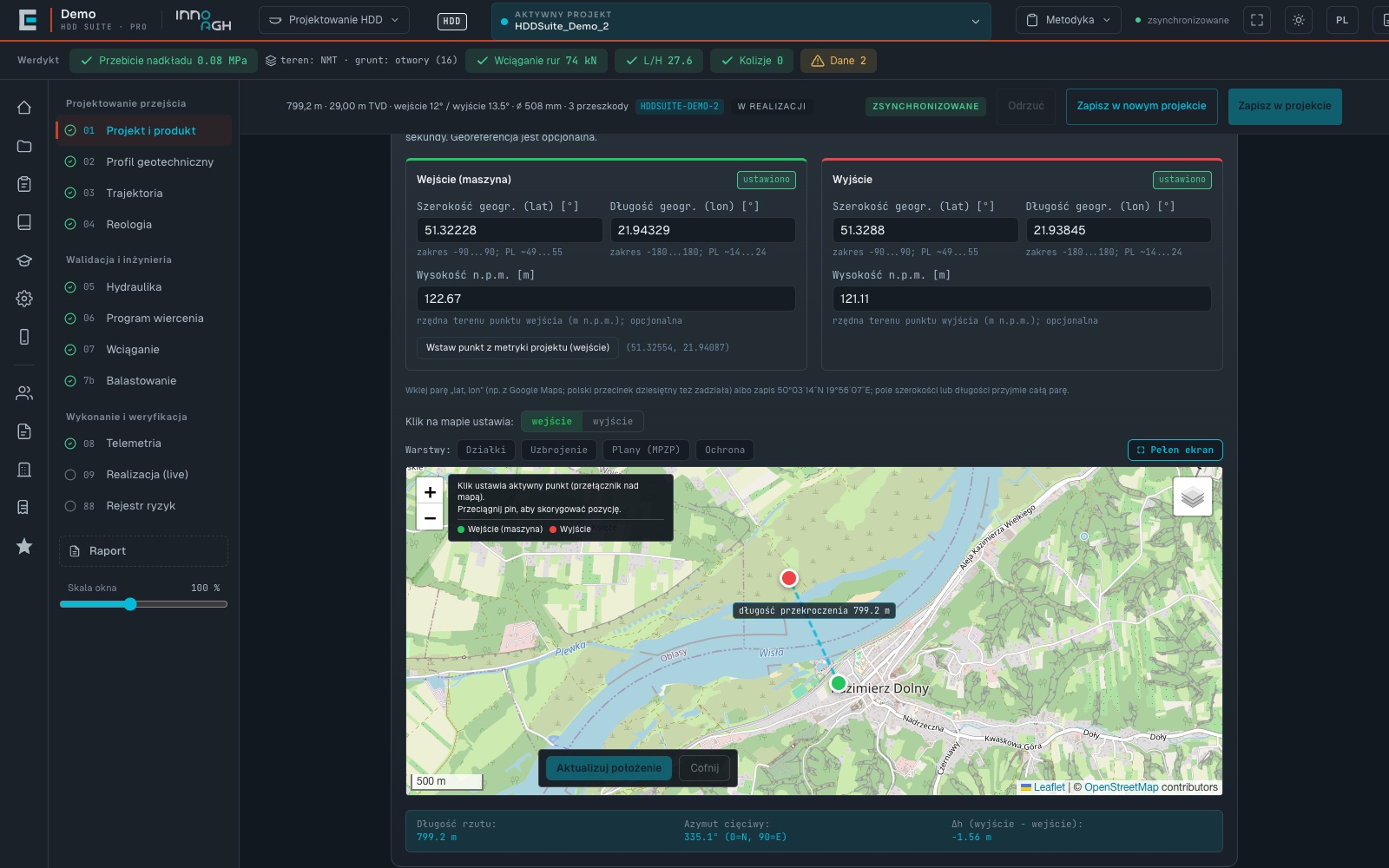
A project starts on the map. The designer places the entry and exit points, and the program derives the route length and azimuth and suggests elevations from the GUGiK digital terrain model (the Polish national DTM). The product pipe is defined at this stage as well (PE, steel, ductile iron or PVC), with steel grades from L245 to L485. The material sets the default minimum bending radius: 40·OD for PE, 1200·OD for steel, 200·OD for ductile iron and 60·OD for PVC. Next to the form, the crossing is classified according to ST-IGG-3301:2021, with the HDI index, project category and normative difficulty grade.
Ground from boreholes, terrain from the DTM
The geotechnical profile is built from boreholes imported from CSV. Layers are interpolated between boreholes linearly or with monotonic PCHIP, and non-parallel layers with varying thickness and pinch-outs are supported. Overburden stress is calculated separately at every station as the sum of layer weights. The program also checks the completeness of the site investigation against Annex I of ST-IGG-3301.
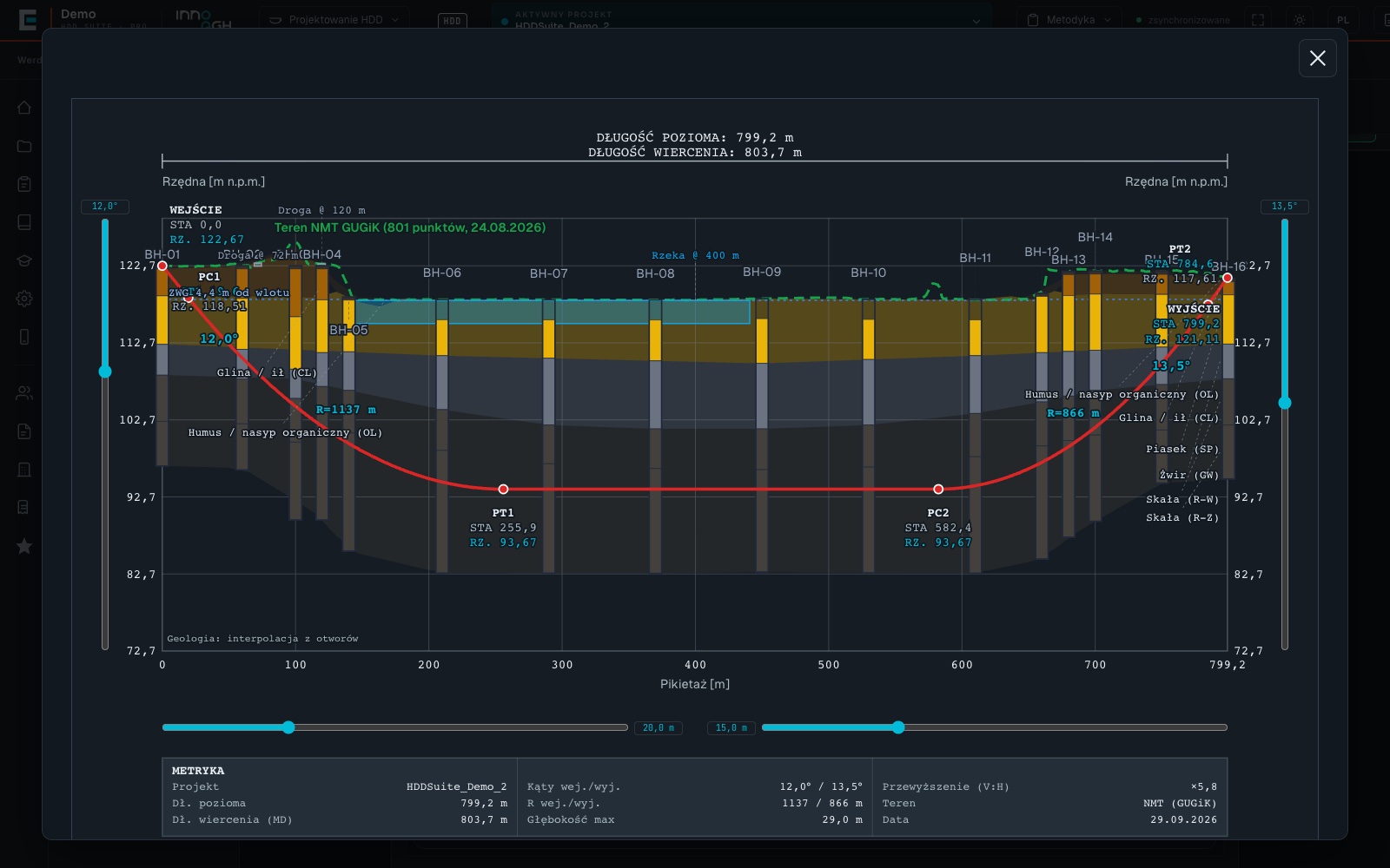
Terrain can be modelled in four ways: flat, inclined, from borehole elevations or from the DTM. The last option matters for river crossings. In a demonstration project under the Wisłoka river, calculations on flat terrain showed a safe result over the channel. With the real DTM profile loaded, the program found hydrofracture at seven stations, because the valley removes about 13 m of ground cover regardless of the depth of the bore axis.
Trajectory in 2D and 3D
The trajectory is a five-segment model: entry tangent, arc, horizontal section, second arc and exit tangent. The longitudinal section is laid out as a contract drawing with a double elevation axis, arc stationing, radii and adjustable vertical exaggeration. It is complemented by a plan view and an MD-Inc-Az-TVD-N-E station table exported to CSV for the steering operator.
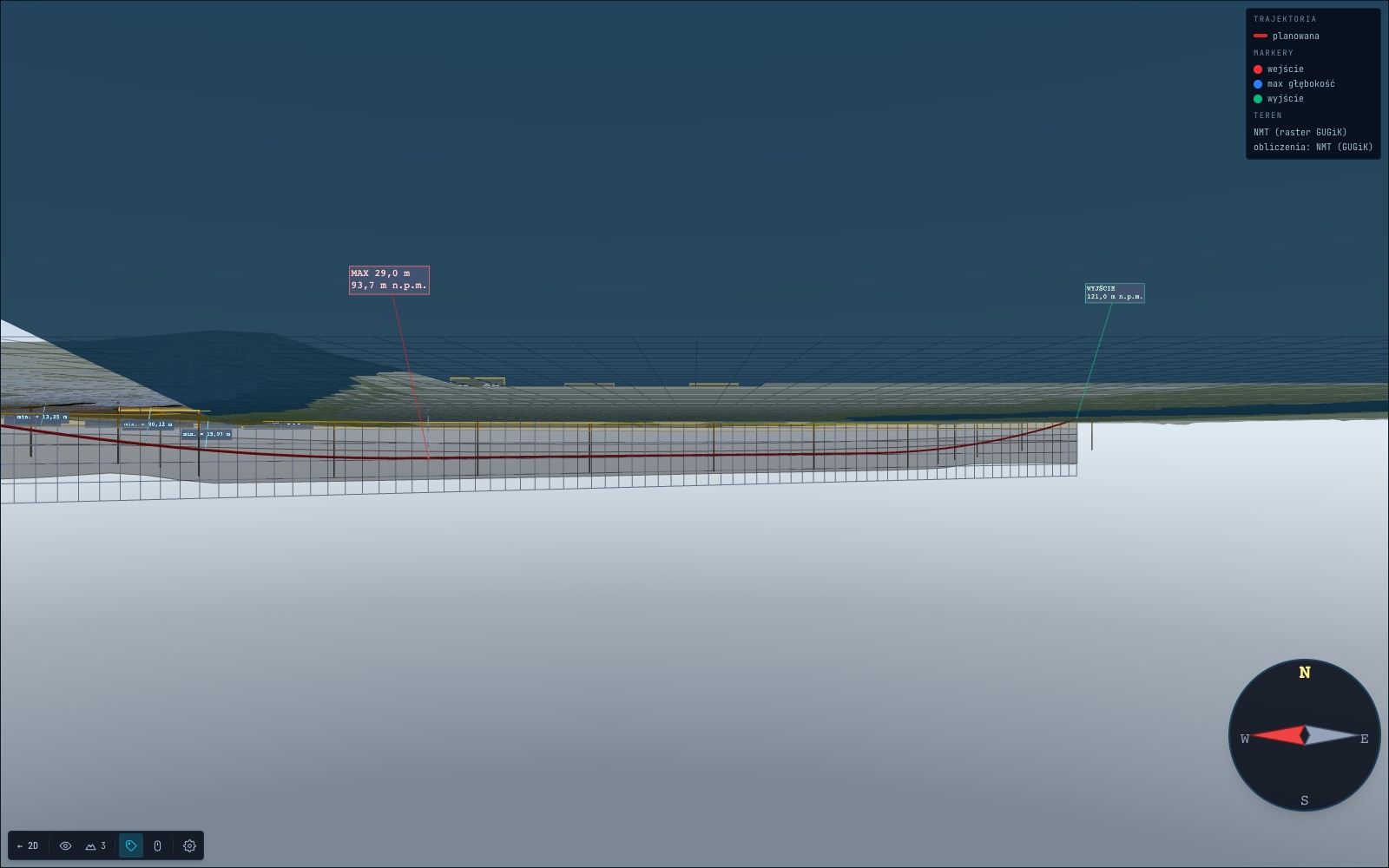
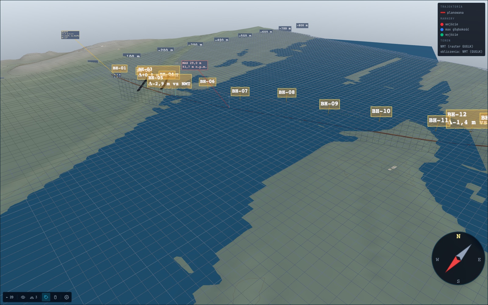
The 3D scene shows the crossing at 1:1 scale: terrain relief from the DTM raster, the river channel, soil layers, boreholes and obstacles. For obstacles the program checks vertical clearance: 1.5 m below a riverbed, 1.0 m below a road base, 2.5 m below a railway embankment, 1.5 m from a pipeline and 5.0 m from a power cable. Formal requirements, such as the 50 m zone from a riverbank under Polish water law or 15 m from a track axis, are kept separate from the technical clearance.
Drilling fluid, pressures and hydrofracture
In the rheology step, drilling fluid parameters are determined from Fann viscometer readings with the Bingham and Herschel-Bulkley models, including the Zamora-Power estimator from the 600, 300, 6 and 3 rpm readings, together with the API RP 13B-1 indicators. Hydraulics are calculated separately for the pilot hole and each reaming pass: annular velocity, pressure loss, ECD and bit nozzle loss, with an eccentricity correction after Haciislamoglu and Langlinais.
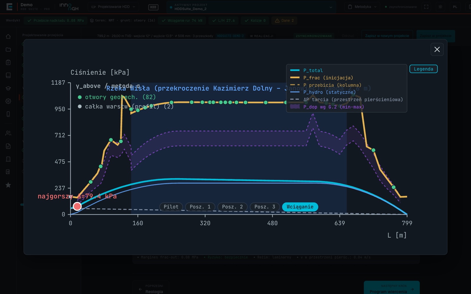
Hydrofracture risk is assessed station by station for piloting, reaming and pull-in. The allowable pressure is calculated with the Delft formula after Luger and Hergarden, with effective stress following Terzaghi's principle (under a river the water column cancels out). A control curve based on the gradients of Annex G of ST-IGG-3301 is drawn alongside, and the share of bore length with sufficient margin is checked.
Pull-in force by four methods
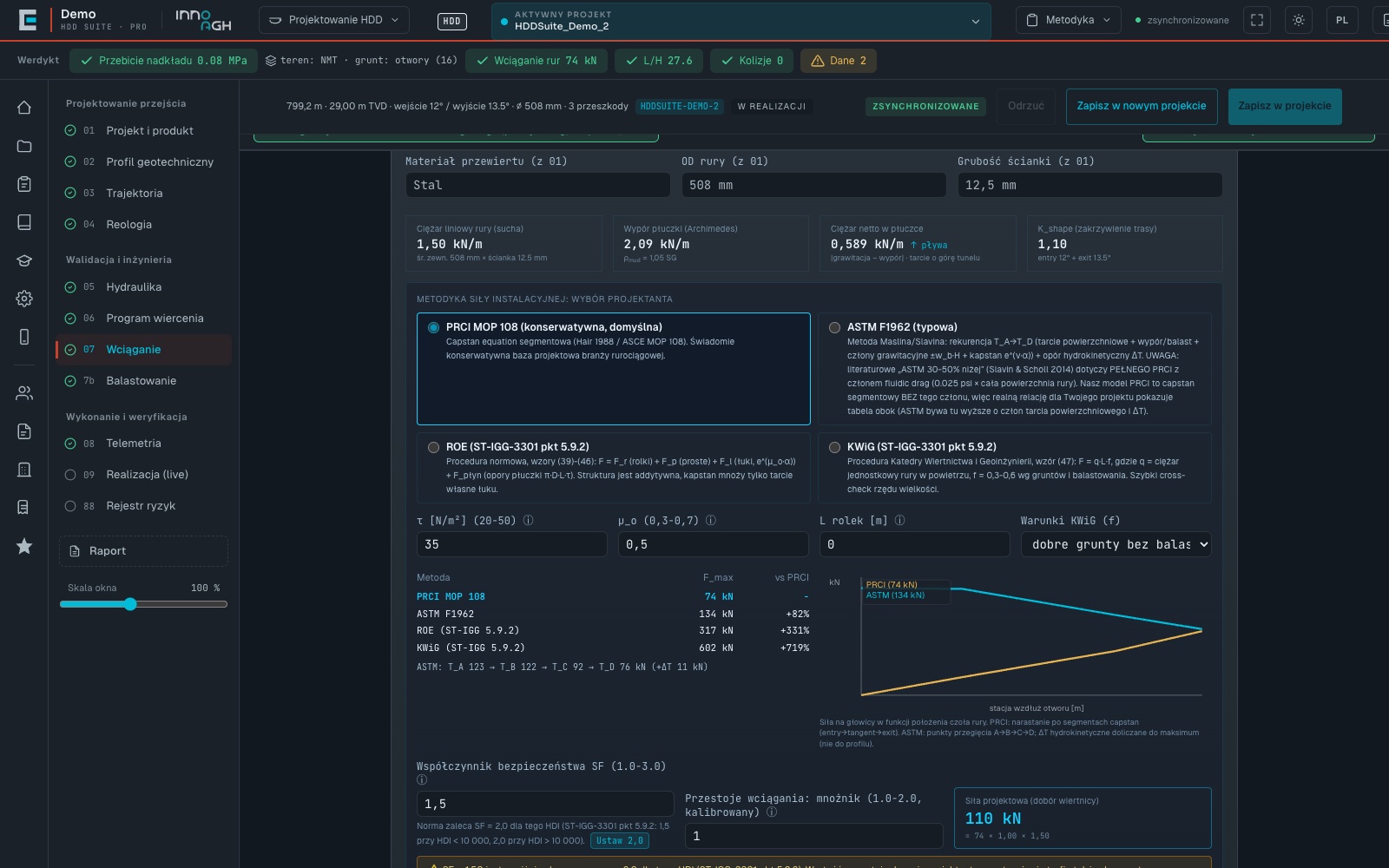
Installation force is calculated in parallel by four methods: PRCI MOP 108, ASTM F1962, ROE and KWiG according to clause 5.9.2 of ST-IGG-3301. The designer selects the one that drives rig class selection and the verdict, and a table shows the differences between results. The design force includes a downtime multiplier and a safety factor. The program also checks pipe stresses, collapse of PE pipe under the drilling fluid column and local buckling of steel. A separate ballasting step compares five pipe-filling variants and recommends the one with the lowest installation force.
From design to site
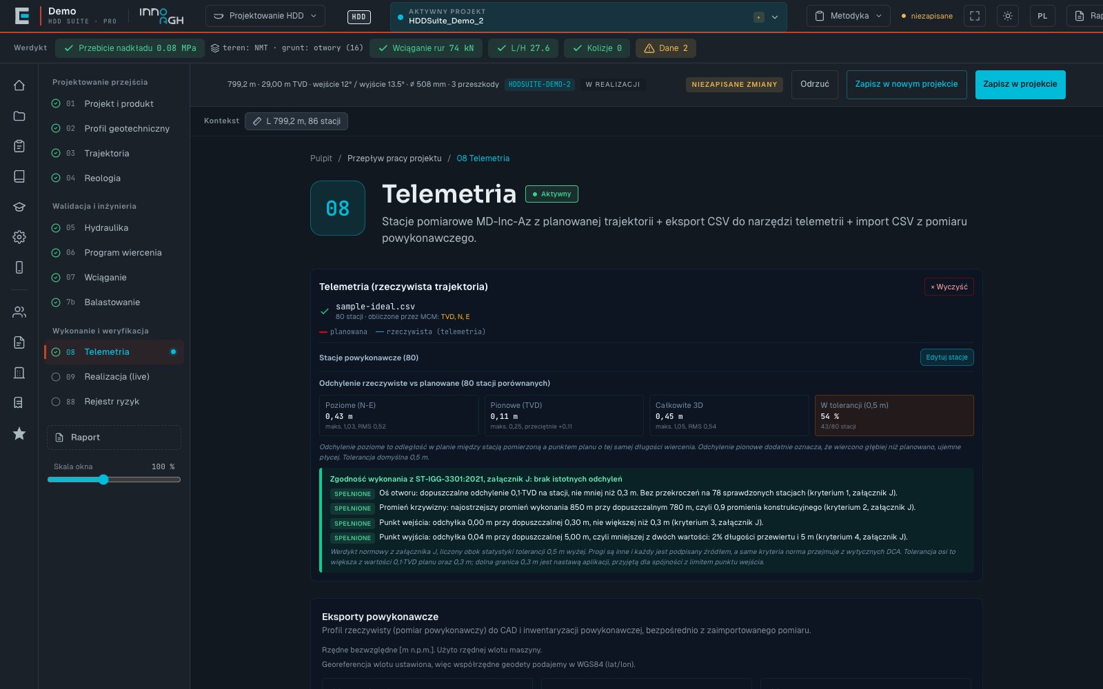
The drilling programme sets out the reaming passes and provides a printable operator card with parameters for every drill rod. After drilling, the designer imports the as-built survey from CSV or from a DigiTrak locating system export. The program reconstructs coordinates with the minimum curvature method, compares the result with the plan and assesses compliance with Annex J of ST-IGG-3301. The as-built survey can be exported to Civil 3D, DXF and CSV for the surveyor.
During execution, a field app on a phone lets the driller, navigator and mud engineer record data rod by rod, including without mobile coverage. The execution panel compares the entries with the plan and runs eight checks on each one, among them deviation, curvature radius, drilling fluid pressure against the hydrofracture limit and force against the forecast. The manual states that this supports decisions and does not control the rig.
Calculation checks and reports
Safety verdicts, including hydrofracture, pull-in force and ballasting, are recalculated in the background by a second, independent calculation engine, and the report includes a comparison table. A data consistency engine assesses the full data set in 21 rule families, for example a reamed hole narrower than the pipe or a borehole elevation that disagrees with the DTM, and reports the problem instead of blocking input.
Reports are produced as PDF in a universal version, a personalised version in company colours and four specialised styles, from a two-page decision summary to a landscape format for the operator on site. A client can receive a read-only link to the project without creating an account.
Beyond HDD, the program has separate workflows for microtunnelling and the Direct Pipe method, as well as educational scenarios following R. Osikowicz's "HDD Planning" series, DCA Europe and ASCE MOP 108. The illustrations come from a demonstration project for a DN500 gas pipeline under the Vistula near Kazimierz Dolny: a fictitious investment on real terrain from the GUGiK DTM, with an 800 m crossing and 16 boreholes.
The publisher of HDDNews.pl is affiliated with the developers of HDDSuite. This article is based on the program documentation and demonstration version.